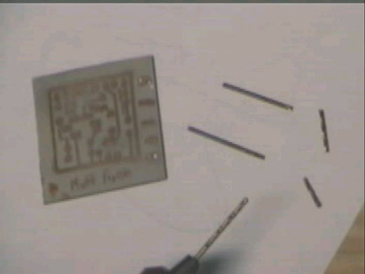
I should have used some kind of
awl or hole
punch, but instead I decided to
use the second drill bit to indent the board. Needless to
say, that bit didn't last long
either. I tried the next smallest size, which worked well,
though it may be good for off-board
wiring, it is too big for most components.
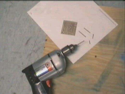
The other thing I realized when
reading JD's site, is that I didn't reverse the image or
anything. So how do I solder the
board once it is drilled? Is the copper side going to be
the component side as well? I'm
sure if I look at it I could figure it out.