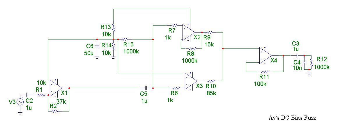
Here's the schematic:
Note: On my actual circuit R2 is 200k pregain
pot;
R9 and R10 is one 100k pot wired as a mixer;
Instead of R12, a 200k pot is wired as the
usual volume control.
R11, C3, and C4 are all socketed (as there
were pins left in the IC socket).
I used an LM324, any quad (single or double)
opamp(s) should do.
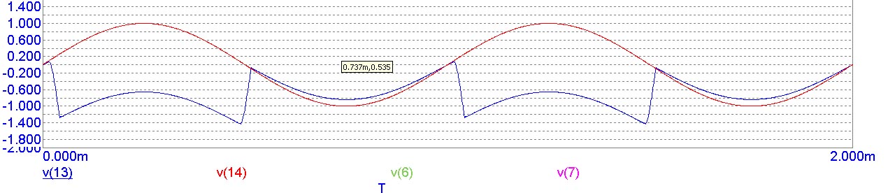
Simulation:
The Input is the red sine wave.
The ouput is the blue trough and peak shifted
sine wave.
More analysis to follow...but it's past midnight and I've been playing
with it all day.
It's time to give it a rest. The circuit works as simulated,
and is very harmonically rich!
By my calculations at 1kHz, 203% total harmonic distortion.
And ~60% intermodulation distortion with 1kHz and 1.7kHz.
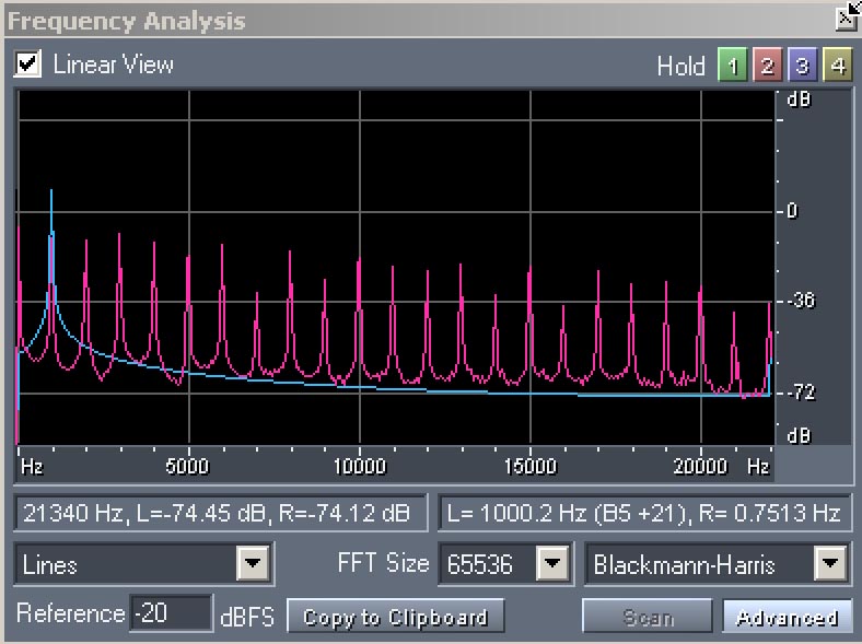
Here we have a sine input at 1kHz (blue) and the output in red.
Note that the third harmonic is louder than the fundamental!
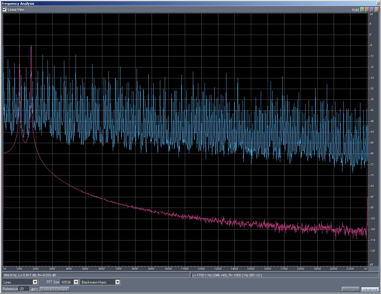
In red are sine waves at 1kHz and 1.7kHz.
In blue is the intermodulation distortion all across the board.